Layout Photos added 2/3/10
Building Summit Trestle
| This photo from January of 1999 shows the earliest planning for Summit Trestle. The upper track will curve across the majestic trestle and the lower tracks will be hidden inside a tunnel in a mountain. The curved plywood on the bottom will support the footers for the trestle bents. |

|
| Supporting ribs have been added for the mountain in this photo from April of 2000 (note that the lower tracks are now behind the future hillside). A masonite fascia board has been added to define the slope on the left side and the footers for the bents are being installed. Note the cardboard mockup of the bent slope angle on the right. This was used to locate the footers and to decide how wide they needed to be. |

|
| Here is the same scene from May of 2000 with hardshell added to the mountain. The temporary plywood and Homasote trestle supported by a few 1x3's was in place for many years. Finally in the Summer of 2007 it was time to build the real trestle. |

|
| The first step was to collect the necessary lumber. Using PRR trestle plans from the year 1925, we would need dimensions of 10x20, 14x14, 12x12, 6x10 and 3x10. A friend and I ripped all of this lumber from 1x3 clear poplar boards using a table saw with a veneer blade. The white stips have the scale lumber dimensions written on them. |

|
| The trestle lumber was all stained after cutting to length but prior to assembly. I used a mix of black and brown leather dye (from a shoe repair shop) thinned with denatured alcohol. The alcohol dries quickly and will not warp the wood. Note that the dispatcher's desk did double duty as the staining work table! |

|
| I made a jig out of 0.040" styrene with other styrene blocks glued on. This guaranteed that all trestle bents would have the same spread angle and the cross braces would all line up. |

|
| The distance between horizontal braces and the cross-bracing pattern were determined using the prototype trestle plans from 1925. My bents have less spread at the base than the plans called for but the overall result is pleasing. Here are some horizontal braces and cross braces weighted down in the jig while the glue dries. The entire trestle was constructed using Elmer's Carpenter's Glue (the yellow stuff). |

|
| Since so many horizontal braces would be needed, I cut and stained a bunch of them in advance. Note that there are lots of short braces (used on all bents) to the right and progressively fewer longer braces (since there are fewer tall bents) as you move to the left. |

|
| Here are a couple of nearly completed bents. They still need timber footers on the bottom and the one on the right still needs a 14x14 cap piece. At the lower right is an assembled but not yet stained curved stringer to go under the ties of the trestle. The stringer is made from 3 pieces of 10x20 scale lumber that are laminated together. To get the curve, I applied glue to the 3 pieces then C-clamped them to the inside radius of the temporary plywood/Homasote curved trestle. When unclamped, the stringers tended to "relax" a little which made the resulting curve just about right. |

|
| Here's the temporary trestle a few years after the hardshell photo above. Scenery has been added to the mountain and the footers have been painted concrete. The scenery had to be completed before the trestle was installed in front of it! At the far left, a small section of the temporary trestle has been removed and short sections of curved stringers and the first few bents are in place. |

|
| Here is a closer shot of the first few bents in position. |

|
| The next step was to remove the next section of temporary trestle to the right of those first bents... |

|
| ... and add the bent at the end of the new stringer pieces. The stringers have butt joints centered on top of a bent. Note that a few more bents have also been added on the left. |

|
| The wall bracing was held in place using plastic clothespin-like clamps while the glue dried. Bracing was added working back to front. The clamps are holding the rear wall bracing between the far right pair of bents. Just to the left, you can see the rear wall bracing and the lateral bracing have been installed. At the far left, the front wall bracing has also been completed. The plans call for 3 bents with wall and lateral bracing, then a gap with lateral bracing only, then another 3 bents with wall and lateral bracing, etc. |

|
| Here the bents have been installed up to the end of the curved stringer and in fact the next piece of curved stringer has been added. |

|
| The bent at the end of the new stringer sections is installed. The C-clamp is holding the stringer in place under the track. After the trestle was installed, the ties in the track were nailed into the stringers. No glue was used here so that the track would be removable if needed. Those big bents would take a LOT of lumber! |

|
| The wall bracing is complete on the largest bents, you can see the end of the project from here! Also note that the next section of the temporary trestle has been removed. |

|
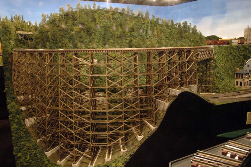
| The backside of the trestle is rarely seen. Too bad, as it looks pretty good! |

|
| The East end of the trestle leads into a pair of deck truss bridges supported by a double bent. The deck trusses were built from a kit by Black Bear Construction Co. and took 2 weeks to construct. |
|
| Finally, here is the proud builder of Summit Trestle admiring the finished product. |

|